This project started as a small idea several months ago for led overalls to attend a new years eve(and other) party with. The idea was simple enough: grab some white overalls, wire them up with LED’s and a controller, then go adventure and ‘wow’ some people! heh, easier said than done..
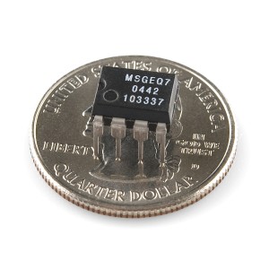
I never really had a very specific design in mind until much later in the build process(maybe a bad idea..xD). It all sort of started when I arrived home for the December holidays, to find some MSGEQ7 chips in the post:
These little guys breakup any audio signal fed into them into 7 bands each represented by a voltage. I quickly grabbed some example arduino code, setup my breadboard with a couple strips of LED’s.
Amazingly it worked quite easily! I had a little bar graph display out of LED’s going to the music! simple, and PERFECT for an led suit I thought! Now all I needed to do was control a bunch more LED’s! Luckily I had a bunch of TLC5947 24-channel 12-bit PWM LED driver chips that I’ve been meaning to try out for ages! only problem:
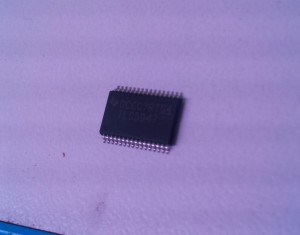
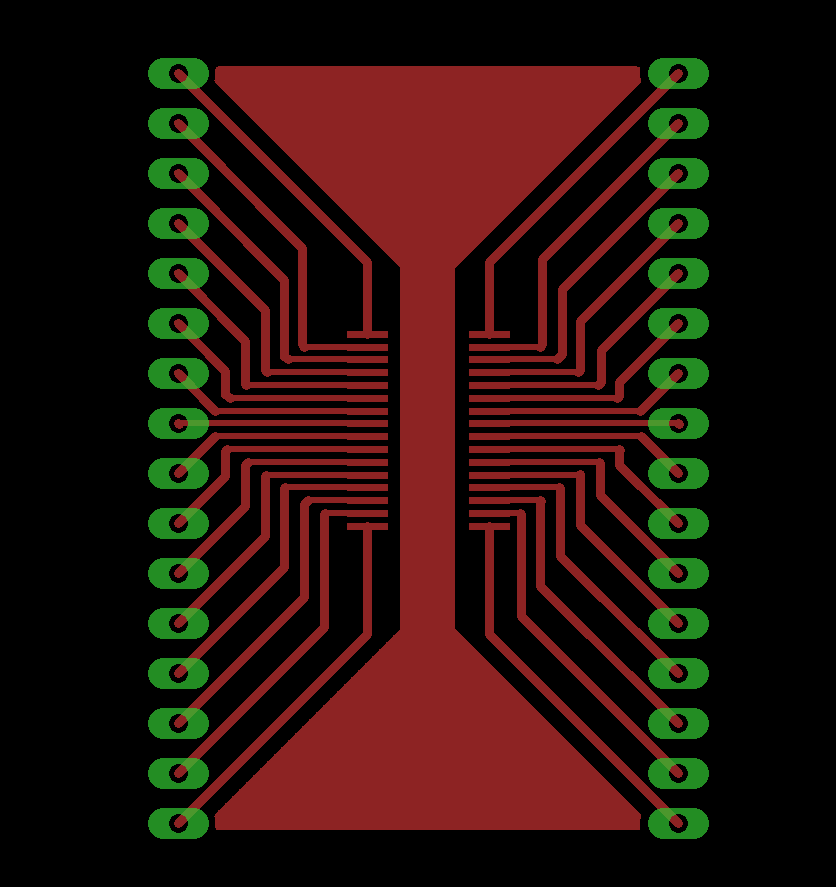
The largest package this IC comes in is the itty bitty 32-pin HTSSOP package… Ok fine, over at Pro-Tec we have capability to make PCB’s thus it was time for my first experiment in designing a breakout board… I just needed to breakout the TLC5947 pins to standard pin headers and place in my breadboard to have a play with it. I started by grabbing the footprint from RazorConcepts(thanks for putting that up! 😀 ) then created the board in Eagle :
Nothing special.. But I’ve made the eagle files available here for any of you that would like to make the same breakout boards 🙂
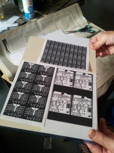
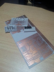
Next was to actually make the boards, quick explanation of the process: we start by printing a negative of the copper tracks and pads on some Mylar film with a standard laser printer(with the darkest settings possible), this is then placed on top of some copper clad PCB with a special photographic film applied. The board is then exposed to strong UV light for ~2min (this can even be done in the sun!), the exposed areas(i.e. tracks) not covered by the black toner on the Mylar ‘harden’. The board is then washed in a slightly basic solution of soda ash and water removing the un-exposed film. Next we place the boards in a solution of hydrochloric acid, hydrogen peroxide and water to etch away the exposed copper. Finally the boards are placed in a strong alkaline solution of caustic soda and water to remove the exposed film and then washed in water and drilled to give the final product…
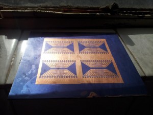 Just after removing the un-exposed film
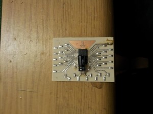
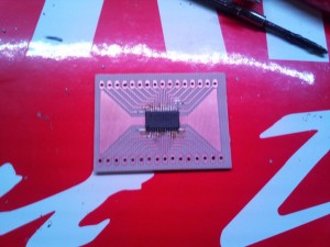 Finally board cut and drilled and TLC5947 soldered.
This was the first time I’ve soldered such a tight pitch SMD part, it was certainly tricky but not too bad with a good soldering iron, solder, a bit of extra flux and decent solder wick. I used the ‘drag soldering’ method, lotsa guides available if you’re friends with google 🙂
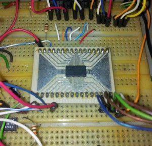
Next up was to get it into the breadboard, wired up as per datasheet and grab some more arduino sample code for quick prototyping…
Annnnd, it works! I could now control 24 channels of LED’s with 12-bits of precision (that means I have 4096 different brightness ‘settings’ for EACH CHANNEL!) These TLC5947’s are really awesome because they can be ‘daisy chained’; basically the first 5947 needs 4 IO pins on your micro of choice, and then each additional 5947 can be connected to the last to expand the number of channels by 24 each time.
Now the idea for these LED overalls was really starting to form, multiple channels of (RGB)LEDS allowing each channel to be any color at any time, all linked up to the music! EPIC! I wanted to use LED strip because it’s pretty resilient, easy to work with(can be cut to length) and reasonably inexpensive. I selected RGB led strip with a density of 30 led’s per meter (5050SMD) (around 7.2W of LEDS!!!) which is the lowest density we carry.. each strip runs off 12V DC and has current limiting resistors built in, as well as a channel for each color: Red, Green and Blue. Thus 3 channels per strip, 24 channels per 5947, 24/3 = 8! I can run 8 ‘segments’ of RGB strip off each controller with each strip being individually controlled!
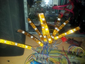
Next up I quickly hacked the MSGEQ7 and TLC5947 arduino code I had together to create a small rainbow ‘bar graph equalizer’ with 8 small pieces of LED strip…
A little messy, but It’ll do for testing! Unfortunately I dont have a vid of it in action… but it was time to move to phase TWO! 😀
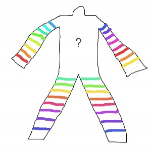
This AWESOME piece of art (lol xD) roughly depicts my original idea for the suit, with one TLC5947 per limb controlling 8 individual sections of strip each. I have 10 TLC5947 in total and I wanted to make two suits (so I could stare at a friend instead of myself when we are out xD) leaving one controller for the chest/back area, however I have no idea what to do there yet… (spiral maybe?)
The next problem I ran into was actually controlling the strip. The TLC5947 are designed to run discreet LED’s or strings of LED’s with no current limiting resistors, to elaborate: the 5947 has built in current limiting on each channel that can be selected, in a range of about ~1-30mA by a reference resistor on one of the pins, It can also only sink current. Now most common LED strip is common anode, i.e the positive side of the LED’s are connected together and the cathodes or negative sides are separated into red, green and blue. Unfortunately this means the 5947 can only provide max ~30ma for each color on each strip, and by my measurements a single 3 LED segment of strip consumes ~20mA @ 12v. For the widest leg pieces I would need about 6 segments of strip to encircle the leg, requiring about ~120mA per color, thus the 5947 would not be able to light the strip to full brightness on its own.. :/ Problem.
The first obvious solution was to drive each channel from a common NPN transistor, however since the 5947 can only sink current, the transistor would require a pull up resistor to turn it on as well as creating a logic inversion in operation(max brightness of 4095 in code would result in the LED’s being off in reality) This is not ideal… 🙁
The solution I came up with was a bit cheeky, but would have to do with NYE about a week away. It so happened we had received an incorrect shipment of common cathode (cathodes or negative tied together and anodes or positive broken out) LED strip from our supplier that was just lying around as its not compatible with our common anode LED controllers, this allowed me to use discreet PNP transistors to drive each channel, which would be ‘turned on’ directly with the 5947’s!
Now usually when working with transistors you need a base current limiting resistor and depending what you’re driving it from a pull-up/down resistor to make sure the transistor is off when it should be, however I was planning on having 5 x 24 channels = 120 transistors PER SUIT! now if I had both resistors that would be 3 solder joints per transistor + 4 solder joints for 2 resistors * 240 = 1680 solder connections! (and thats just for the transistors, without the strips!) I don’t have that kinda time o.O However I quickly realized I could get away without the base current limiting resistor by setting the current limit on the 5947 to ~1mA, which shouldn’t damage the transistors! I really should put pull up resistors though, but I figured as long as the transistors base’s didn’t make contact with the human body(big leaky capacitor/resistor to ground xD) they had no other path to conduct through than the 5947! looks like I might just be able to get away with the transistors on their own 😀 8) Lucky break!
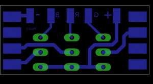
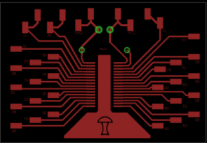
At this point it seemed I needed to design the PCB’s to move forward with the prototype I spent Christmas day designing the following three boards:
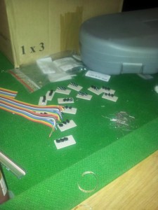
Small connector board, contains the three PNP transistors, allows you to solder the strip on each side to make a ring and has power and signal pads to drive the strip. Nothing fancy 🙂 (I used 2SA1015 transistors)
This is my second TLC5947 breakout board, instead of pin headers it has solder pads that I connect each led channel to with ribbon cable(saves a huge amount of time over manually drilling holes) it also has a location for current setting resistor and a small filter capacitor on the supply pins. Dual pads are available on each control pin for daisy chaining devices, as well as a -small- heat pad under the 5947, thou I doubt its effectiveness in most situations… xD
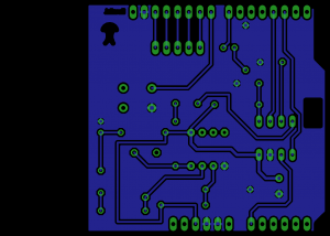
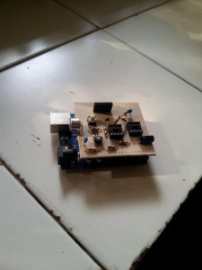
Ah now before we get onto the last board, let me tell you a bit more about the main control circuit, While I’m not the worlds biggest arduino fan, I dont deny its speed of prototyping, and was in great need of time! So to simplify matters I decided to stick the the arduino for now (although I will probably port this project to an MSP430 in the future 🙂 ) also instead of designing a main control board from scratch, I thought I’d try my hand at creating my first arduino shield. This also allowed me to take advantage of the arduino’s voltage regs, crystal oscillators, usb programming, etc etc.
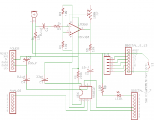
The circuit itself is relatively simple: (excuse the untidy schematic, I was rushing.. which really is no excuse xD)
A simple electet mic feeds an op-amp(lm358) setup in inversion mode, a 100k pot sets the gain from 1-101, this signal is then passed to the MSGEQ7 which is read by the arduino, some magic then happens in code and data is sent out to the 5947’s. there is also a little momentary switch for changing modes, a status led and a supply filter cap.
The shield once I had laid it out.
Next it was off to work to do some etching:
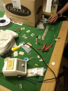
Assembly:
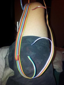
^^ FINISHED LEG! 😀 ^^
Testing: (ignore the BirdMan)
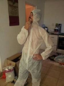
My side-kick was supposed to arrange proper workforce style white overalls, but unfortunately he left it a bit late into the holiday season. We could only get these disposable ones for new years, our plan is to sew the LED’s on the outside and then put another overall over them to hide them. Upside of this is we can keep the LED’s on the inner disposable overall and once we acquire the correct overalls, we can just wear those on the outside 😀
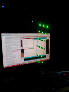
Quick vid of the testing:
More to come in Part2 !! including; (semi) finished Pics, videos of it in action, board files and source code 🙂
More vids:

Leave a Reply